
experience summary of crane girder design
Crane Girder Load Analysis & Design
There will be three directions of dynamic load when the crane in running on the crane girder: vertical load, horizontal load, and horizontal load along the longitudinal direction of the crane girder.Longitudinal horizontal load is the crane’s braking force, which is supported by the crane girder along the rail direction, and is not considered when calculating the cross of the crane girder. The standard value of the crane girder vertical load should be used for maximum wheel pressure and minimum wheel pressure. The crane girder vibration will be caused when the crane is running along the rail, lifting, unloading, and reversing the workpiece. Especially when the crane crosses the rail joint, the impact will also occur. Therefore, in the calculation of the crane girder and its connection strength, the crane vertical load should be multiplied by the dynamic coefficient. For the suspension crane (including electric hoist) and the soft hook crane, whose working class is around A1~A5, the dynamic coefficient is desirable 1.05; for the soft hook crane, hard hook crane and other special crane, whose working level is around A6~A8, the dynamic coefficient is desirable 1.1.
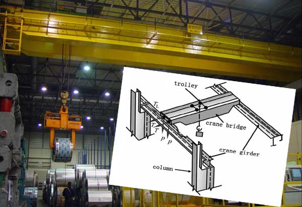
P: vertical load
L: horizontal load
TL: horizontal load along the longitudinal direction
L: horizontal load
TL: horizontal load along the longitudinal direction
The crane horizontal load is caused by trolley, the standard value shall be the sum of the weight and the percentage of the rated load, and multiplied by the acceleration of gravity:
- Soft hook crane: When rated lifting weight is not more than 10 tons, we should take 12%; when rated lifting weight is 16 ~ 50 tons, we should take 10%; when rated lifting weight is not less than 75 tons, we should take 8%.
- Hard hook crane: We should take 20%. The horizontal load should be equal to the ends of the bridge, transmitted respectively from the track wheel to track average, Its direction is perpendicular to the track, and the brake condition should be considered on both the positive direction and the opposite direction. The horizontal load of the suspension crane should be borne by the supporting system, and can not be calculated. The horizontal load on manual crane and electric hoist will not be considered.
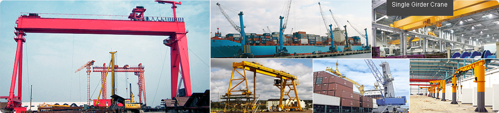
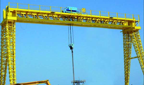
Crane Girder Forms
Crane girder should be able to withstand the load generated during the use of the crane. Bending moment and shear force are caused in vertical direction of crane girder by the vertical load, on the contrary, they will be caused in the crane upper flange plane by the horizontal load. Crane's lifting weight and span of crane girder determine the form of crane girder. Crane girder is generally designed as simply supported beam, continuous beam design can save material, but the continuous beam is sensitive to the support settlement. As for the common section form of crane girder, the I steel, H steel, welding I-steel, box girder and truss can be used as crane girder. Trussed construction crane girder can save steel, but the manufacture wastes time, connection is also easy to produce endurance failure under dynamic loads, so it is generally used for light and intermediate crane girder with smaller span. In the case of small span and weight (span is not more than 6 meters, the weight is not more than 30 tons), the crane girder can resist horizontal load by welding steel plate, angle steel and channel steel on the flange plate.
trussed construction crane girder

I steel crane girder design
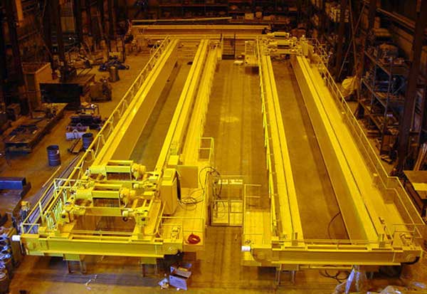
For a crane girder with a large span or a larger weight, the brake structure is provided, that is, the brake beam or the brake truss; the braking structure transmits horizontal load to the column, while ensuring the overall stability of girders. The width of the brake beam should not be less than 1~1.5 m, brake truss should be used when the width is larger. The upper flange of the crane beam acts as a flange or a chord member of the brake structure, the brake structure of another flange or chord can adopts channel steel or angle steel. Brake structure can also act as a maintenance corridor. Therefore, the brake girder web generally adopts the pattern plate, and thickness is 6~10 mm. For the span is greater than or equal to 12 meters of heavy duty crane girder, or the span is greater than or equal to 18 meters of light and intermediate crane girder, it should set the auxiliary truss and the lower flange (bottom) horizontal support system, at the same time set the vertical support. What’s more, its position should not be located in the maximum deflection of the beam or truss, so as to avoid excessive force caused damage.
Crane Girder Design
Reasonable Crane Girder Structure Design
Stress connection is the main cause of fatigue damage, therefore, we should pay special attention to the detail structure design of crane girder. Using a layer of steel is suitable for welding flange of the composite crane girder. When using two layers of steel plate, the outer plate should be set up along the girder, and measures should be taken in the design and construction to make the upper flange of the two layer contacts closely with the upper flange. Welding an joint of crane girder flange or web should be used with arc plate and lead plate penetration welds. The cutting place of the lead plate and arc plate should be polished smoothly.The crane girder welding and the crane truss welding should be adopted the fraction type connection with high – strength bolts.
The width of the lateral stiffening rib of the crane girder should be not less than 90mm. The transverse stiffening ribs at the supports should be arranged at both sides of the web, and should be pressed tightly with the upper and lower flange plane girder. The upper end of the middle transverse stiffener should be pressed tightly with the upper flange plane girder, as for heavy duty crane girder, intermediate transverse stiffening ribs are arranged on both sides of the web. However, the intermediate and light crane girder can be set unilaterally or be set staggered. When welding crane girder, the transverse stiffener should not be welded with the pulled flange, but can be welded with the pressed flange. End stiffening rib can be welded with the upper and the lower flange. The lower end of the intermediate transverse stiffening rib is appropriate to be disconnected from the lower flange of the 50~100mm, but its connection with the web is not suitable for the landing of the rib at the lower end of the rib. When the crane girder is connected with the support of the flange, the welding connection is not suitable.
As for heavy duty crane girder, the friction type connection of the high strength bolt is suitable for the connection of the transmission between the upper flange and the column or the brake truss. But as for the upper flange and the brake girder connection, we can adopt the high strength bolt friction type connection, or welding joint.
The connection between the ends of the girder and the column should be managed to reduced the additional stress generated at the joint, because of the crane girder bending deformation. The tensile flange of crane girder should be rolled edge or automatic cutting edge. When using the manual gas cutting or cutting machine cutting, it should be beveled along all of the length. The parts, which are used to hung the equipment are not allowed to be welded on the upper and lower flange of the crane girder, strike fire and welding fixture are also disallowed.
Crane Girder Internal Force Calculation
As the crane load is moving load, at first, we must use the mechanical method to determine the most unfavorable wheel pressure position (bending moment and shear force) of the maximum internal force of the crane beam when calculate the internal force of the crane girder. Then the girder maximum bending moment and the corresponding shear force and the girder maximum shear force and the corresponding bending moment, as well as the maximum bending moment of horizontal load in horizontal direction, are obtained respectively.experience-summary-of-crane-girder-designWhen calculating the fatigue and deflection of crane girder, they should be determined by the crane whose load effect is the largest, and be calculated according to the characteristic value of load without the load factor and partial safety factor for load. Then the cross section of the beam and the brake structure are selected after the most unfavorable internal force is obtained.